Capacitors and Their Combinations
A Comprehensive Guide for IIT JEE, NDA & Other Competitive Exams
1. Introduction to Capacitors
Capacitors are fundamental passive electronic components used in a wide range of electrical and electronic circuits. They store electrical energy in the form of an electric field between two conductive plates separated by an insulating material called a dielectric. Understanding capacitors and their behavior is crucial for grasping advanced concepts in electrostatics and circuit theory—topics frequently tested in competitive exams like IIT JEE and NDA.
Important Note:
Capacitors appear in approximately 15-20% of the electrostatics questions in IIT JEE Advanced and are frequently combined with other circuit elements in problems that test multiple concepts simultaneously.
2. Definition and Working Principle
A capacitor is a two-terminal electrical component that stores electrical energy in an electric field. The basic structure consists of two conducting plates separated by a non-conducting material (dielectric).
Working Principle:
- When a voltage is applied across the terminals of a capacitor, positive charge accumulates on one plate and negative charge on the other.
- The plates attract opposite charges but the dielectric prevents these charges from flowing between the plates.
- An electric field is established in the dielectric medium between the plates.
- Energy is stored in this electric field.
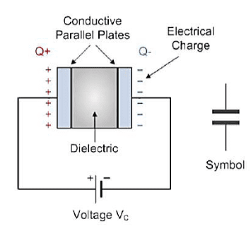
Fig 1: Basic structure of a parallel plate capacitor showing the conducting plates and dielectric
3. Capacitance and Units
Capacitance is the ability of a capacitor to store electrical charge for a given potential difference between its plates.
The capacitance \(C\) is defined as the ratio of the magnitude of charge \(Q\) on either conductor to the potential difference \(V\) between the conductors:
\( C = \frac{Q}{V} \)
Where:
- \(C\) is the capacitance measured in farads (F)
- \(Q\) is the electric charge measured in coulombs (C)
- \(V\) is the potential difference measured in volts (V)
Units of Capacitance:
The SI unit of capacitance is the farad (F), named after Michael Faraday. A capacitor has a capacitance of one farad when a charge of one coulomb produces a potential difference of one volt across its plates.
Since the farad is quite a large unit for practical circuits, smaller units are commonly used:
| Unit | Symbol | Equivalent |
|---|---|---|
| Microfarad | μF | 10-6 F |
| Nanofarad | nF | 10-9 F |
| Picofarad | pF | 10-12 F |
4. Parallel Plate Capacitors
The parallel plate capacitor is the simplest and most fundamental form of a capacitor, consisting of two parallel conducting plates of equal area separated by a dielectric material.
4.1 Capacitance Without Dielectric Medium (Vacuum)
For a parallel plate capacitor with vacuum between the plates, the capacitance is given by:
\( C = \frac{\varepsilon_0 A}{d} \)
Where:
- \(\varepsilon_0\) is the permittivity of free space (\(8.85 \times 10^{-12} \text{ F/m}\))
- \(A\) is the area of overlap between the plates (in m²)
- \(d\) is the distance between the plates (in m)
4.2 Capacitance With Dielectric Medium
When a dielectric material is inserted between the plates, the capacitance increases by a factor known as the relative permittivity or dielectric constant (\(K\) or \(\varepsilon_r\)) of the material.
For a parallel plate capacitor with a dielectric medium, the capacitance is given by:
\( C = \frac{\varepsilon_0 \varepsilon_r A}{d} = \frac{KA\varepsilon_0}{d} \)
Where:
- \(\varepsilon_r\) or \(K\) is the relative permittivity or dielectric constant of the material
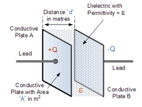
Fig 2: Parallel plate capacitor with dielectric material
Common Dielectric Materials and their Dielectric Constants:
| Material | Dielectric Constant (K) |
|---|---|
| Vacuum | 1.0 |
| Air | 1.00059 |
| Paper | 2.5-3.5 |
| Glass | 4-10 |
| Mica | 5-7 |
| Water | 80 |
| Ceramic | 20-12000 |
5. Derivation of Capacitance Formula for Parallel Plate Capacitor
Let’s derive the formula for the capacitance of a parallel plate capacitor step by step:
- Consider two parallel plates with area \(A\) separated by a distance \(d\) in vacuum.
- Let the charge on one plate be \(+Q\) and on the other be \(-Q\).
- The electric field between the plates is uniform and given by: \(E = \frac{\sigma}{\varepsilon_0} = \frac{Q}{A\varepsilon_0}\) where \(\sigma\) is the surface charge density.
- The potential difference between the plates is: \[V = E \times d = \frac{Q}{A\varepsilon_0} \times d = \frac{Qd}{A\varepsilon_0}\]
- Capacitance is defined as \(C = \frac{Q}{V}\), so: \[C = \frac{Q}{\frac{Qd}{A\varepsilon_0}} = \frac{A\varepsilon_0}{d}\]
When a dielectric with dielectric constant \(K\) is inserted, the electric field is reduced by a factor of \(K\), and the capacitance formula becomes:
\( C = \frac{KA\varepsilon_0}{d} \)
6. Combinations of Capacitors
In electrical circuits, capacitors can be connected in different ways to achieve specific total capacitance values. The two basic ways to connect capacitors are in series and parallel.
6.1 Series Combination of Capacitors
When capacitors are connected in series, the same charge appears on each capacitor, but the potential difference across each capacitor may be different.
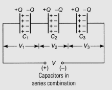
Fig 3: Capacitors connected in series
For capacitors \(C_1, C_2, C_3, …, C_n\) connected in series, the equivalent capacitance \(C_{eq}\) is given by:
\( \frac{1}{C_{eq}} = \frac{1}{C_1} + \frac{1}{C_2} + \frac{1}{C_3} + … + \frac{1}{C_n} \)
For two capacitors in series:
\( C_{eq} = \frac{C_1 \times C_2}{C_1 + C_2} \)
Key Insight:
The equivalent capacitance of capacitors in series is always less than the smallest individual capacitance in the series.
6.2 Parallel Combination of Capacitors
When capacitors are connected in parallel, they all experience the same potential difference, but may hold different charges.
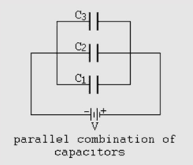
Fig 4: Capacitors connected in parallel
For capacitors \(C_1, C_2, C_3, …, C_n\) connected in parallel, the equivalent capacitance \(C_{eq}\) is given by:
\( C_{eq} = C_1 + C_2 + C_3 + … + C_n \)
Key Insight:
The equivalent capacitance of capacitors in parallel is always greater than the largest individual capacitance in the parallel combination.
6.3 Complex Networks of Capacitors
For more complex networks, the following approach can be used:
- Identify simple series and parallel combinations that can be reduced to equivalent capacitors.
- Redraw the circuit with these equivalent capacitors.
- Continue simplifying until a single equivalent capacitance is obtained.
- For complex arrangements that cannot be reduced to simple series and parallel combinations, use network theorems like Y-Δ transformations or nodal analysis.
Example: Complex Capacitor Network
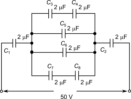
Fig 5: A complex network of capacitors
Find the equivalent capacitance between points A and B in the circuit shown above, where all capacitors have value C.
Solution:
- First, identify that the capacitors in the top branch (C, C) are in series. Their equivalent capacitance is \(C_{eq1} = \frac{C \times C}{C + C} = \frac{C}{2}\).
- Similarly, the capacitors in the bottom branch (C, C) have equivalent capacitance \(C_{eq2} = \frac{C}{2}\).
- Now, \(C_{eq1}\), \(C_{eq2}\), and the middle capacitor C are in parallel. The total equivalent capacitance is: \[C_{eq} = \frac{C}{2} + C + \frac{C}{2} = 2C\]
Therefore, the equivalent capacitance between points A and B is 2C.
7. Energy Stored in a Capacitor
When a capacitor is charged, energy is stored in the electric field between its plates. This energy can be calculated in several equivalent ways.
The energy \(U\) stored in a capacitor is given by:
\( U = \frac{1}{2}QV = \frac{1}{2}CV^2 = \frac{Q^2}{2C} \)
Where:
- \(U\) is the energy in joules (J)
- \(Q\) is the charge in coulombs (C)
- \(V\) is the potential difference in volts (V)
- \(C\) is the capacitance in farads (F)
Energy Density in Electric Field
The energy stored per unit volume (energy density) in the electric field is:
\( u = \frac{1}{2}\varepsilon_0 E^2 \)
For a dielectric medium with dielectric constant \(K\):
\( u = \frac{1}{2}\varepsilon_0 K E^2 = \frac{1}{2}\varepsilon E^2 \)
Where \(\varepsilon = \varepsilon_0 K\) is the permittivity of the medium.
8. Solved Examples for IIT JEE & Competitive Exams
Example 1: Basic Capacitance Calculation
A parallel plate capacitor has plates of area 200 cm² separated by a distance of 2 mm in air. Calculate its capacitance. (Given: \(\varepsilon_0 = 8.85 \times 10^{-12} \text{ F/m}\))
Solution:
Using the formula for capacitance of a parallel plate capacitor:
\( C = \frac{\varepsilon_0 A}{d} \)
Converting to SI units:
A = 200 cm² = 200 × 10⁻⁴ m² = 0.02 m²
d = 2 mm = 2 × 10⁻³ m
Substituting:
\( C = \frac{8.85 \times 10^{-12} \times 0.02}{2 \times 10^{-3}} = \frac{1.77 \times 10^{-13}}{2 \times 10^{-3}} = 8.85 \times 10^{-11} \text{ F} = 88.5 \text{ pF} \)
Example 2: Effect of Dielectric
A parallel plate capacitor has a capacitance of 100 pF in air. When a dielectric is inserted between the plates, the capacitance becomes 500 pF. Find the dielectric constant of the material.
Solution:
We know that when a dielectric of constant K is inserted between the plates of a capacitor, its capacitance becomes K times its original value:
\( C_{with \, dielectric} = K \times C_{without \, dielectric} \)
Given:
\( C_{without \, dielectric} = 100 \text{ pF} \)
\( C_{with \, dielectric} = 500 \text{ pF} \)
Substituting:
\( 500 = K \times 100 \)
\( K = \frac{500}{100} = 5 \)
Therefore, the dielectric constant of the material is 5.
Example 3: Capacitors in Series and Parallel
Three capacitors of capacitances 2 μF, 3 μF, and 6 μF are connected:
(a) Find the equivalent capacitance when they are connected in series.
(b) Find the equivalent capacitance when they are connected in parallel.
Solution:
(a) For capacitors in series:
\( \frac{1}{C_{eq}} = \frac{1}{C_1} + \frac{1}{C_2} + \frac{1}{C_3} \)
\( \frac{1}{C_{eq}} = \frac{1}{2} + \frac{1}{3} + \frac{1}{6} = \frac{3 + 2 + 1}{6} = \frac{6}{6} = 1 \)
\( C_{eq} = 1 \text{ μF} \)
(b) For capacitors in parallel:
\( C_{eq} = C_1 + C_2 + C_3 \)
\( C_{eq} = 2 + 3 + 6 = 11 \text{ μF} \)
Example 4: Energy Stored in a Capacitor
A 5 μF capacitor is charged to a potential difference of 100 V. Calculate the energy stored in the capacitor.
Solution:
The energy stored in a capacitor is given by:
\( U = \frac{1}{2}CV^2 \)
Given:
C = 5 μF = 5 × 10⁻⁶ F
V = 100 V
Substituting:
\( U = \frac{1}{2} \times 5 \times 10^{-6} \times (100)^2 \)
\( U = \frac{1}{2} \times 5 \times 10^{-6} \times 10^4 \)
\( U = 0.025 \text{ J} = 25 \text{ mJ} \)
Example 5: Advanced Problem (IIT JEE Level)
A parallel plate capacitor with plates of area A and separation d is filled with three dielectric slabs of equal thickness d/3 and dielectric constants K₁, K₂, and K₃ respectively, as shown in the figure. Find the equivalent capacitance of the capacitor.
Fig 6: Parallel plate capacitor with three dielectric slabs
Solution:
The three dielectric slabs can be viewed as three capacitors connected in series. Let’s calculate the capacitance of each section.
For the section with dielectric constant K₁:
\( C_1 = \frac{\varepsilon_0 K_1 A}{d/3} = \frac{3\varepsilon_0 K_1 A}{d} \)
Similarly:
\( C_2 = \frac{3\varepsilon_0 K_2 A}{d} \)
\( C_3 = \frac{3\varepsilon_0 K_3 A}{d} \)
Now, for series combination:
\( \frac{1}{C_{eq}} = \frac{1}{C_1} + \frac{1}{C_2} + \frac{1}{C_3} \)
\( \frac{1}{C_{eq}} = \frac{d}{3\varepsilon_0 K_1 A} + \frac{d}{3\varepsilon_0 K_2 A} + \frac{d}{3\varepsilon_0 K_3 A} \)
\( \frac{1}{C_{eq}} = \frac{d}{3\varepsilon_0 A} \left( \frac{1}{K_1} + \frac{1}{K_2} + \frac{1}{K_3} \right) \)
\( C_{eq} = \frac{3\varepsilon_0 A}{d} \times \frac{1}{\frac{1}{K_1} + \frac{1}{K_2} + \frac{1}{K_3}} \)
\( C_{eq} = \frac{3\varepsilon_0 A}{d} \times \frac{K_1 K_2 K_3}{K_2 K_3 + K_1 K_3 + K_1 K_2} \)
Therefore, the equivalent capacitance is:
\( C_{eq} = \frac{3\varepsilon_0 A}{d} \times \frac{K_1 K_2 K_3}{K_2 K_3 + K_1 K_3 + K_1 K_2} \)
9. Practice Problems
Problem 1:
Two capacitors of capacitances 4 μF and 6 μF are connected in series with a battery of 12 V. Calculate:
- The equivalent capacitance
- The charge on each capacitor
- The potential difference across each capacitor
Problem 2:
A parallel plate capacitor with air between the plates has a capacitance of 12 pF. The separation between the plates is 4 mm. If a dielectric of thickness 3 mm and dielectric constant K = 6 is inserted between the plates, find the new capacitance of the capacitor.
Problem 3:
In the circuit shown below, all capacitors have the same capacitance C. Find the equivalent capacitance between points A and B.

Problem 4:
Three capacitors of capacitances 2 μF, 4 μF, and 8 μF are first connected in series and then in parallel. Find:
- The equivalent capacitance in series
- The equivalent capacitance in parallel
- The ratio of the charge stored in the equivalent capacitors when connected to the same voltage source
Problem 5 (Advanced):
A parallel plate capacitor of capacitance C is charged to a potential difference V and then disconnected from the battery. A dielectric slab of dielectric constant K is now inserted so that it completely fills the space between the plates. Find:
- The new potential difference between the plates
- The change in the energy stored in the capacitor
- The work done in inserting the dielectric slab
10. Key Formulas to Remember
- Capacitance: \(C = \frac{Q}{V}\)
- Parallel plate capacitor (vacuum): \(C = \frac{\varepsilon_0 A}{d}\)
- Parallel plate capacitor (with dielectric): \(C = \frac{\varepsilon_0 K A}{d}\)
- Series combination: \(\frac{1}{C_{eq}} = \frac{1}{C_1} + \frac{1}{C_2} + … + \frac{1}{C_n}\)
- Parallel combination: \(C_{eq} = C_1 + C_2 + … + C_n\)
- Energy stored: \(U = \frac{1}{2}QV = \frac{1}{2}CV^2 = \frac{Q^2}{2C}\)
- Energy density: \(u = \frac{1}{2}\varepsilon_0 K E^2\)
11. Conclusion
Understanding capacitors and their combinations is crucial for success in competitive exams like IIT JEE and NDA. The key to mastering this topic is to:
- Understand the basic principles and physical significance of capacitance
- Practice capacitance calculations for different geometries
- Master the rules for series and parallel combinations
- Develop problem-solving skills for complex capacitor networks
- Relate capacitance to energy storage and electric fields
With practice, you’ll find that capacitor problems become more intuitive, allowing you to tackle even the most challenging questions in competitive exams.
