Flow of Electric Charges in a Metallic Conductor
Understanding how electrons move through metals
Table of Contents
Introduction to Charge Flow in Conductors
The flow of electric charges in metallic conductors is a fundamental aspect of electrical engineering and physics. Unlike semiconductors or insulators, metals possess a unique structure that allows for the efficient movement of electric charges, specifically electrons. This charge movement forms the basis of electrical current in circuits.
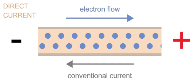
When we connect a conductor to a battery or any potential difference source, electrons begin to flow through the conductor. This flow of electrons constitutes an electric current. The phenomenon can be explained through various physical theories and concepts that we will explore in this article.

Figure 1: Illustration of electron flow in a metallic conductor when connected to a battery.
Electron Theory of Metals
The electron theory of metals, also known as the free electron theory or Drude model, provides a framework for understanding how electric charges flow through metallic conductors. This theory, initially proposed by Paul Drude in 1900 and later refined by others, treats the valence electrons in metals as a “gas” of free particles that can move throughout the metal lattice.
Key Concepts of Electron Theory
- Free Electrons: In a metallic crystal, the outermost electrons (valence electrons) of metal atoms are loosely bound and can freely move throughout the metal lattice.
- Electron Cloud: These free electrons form a “sea” or “cloud” of electrons that surrounds the positively charged metal ions arranged in a lattice structure.
- Random Motion: In the absence of an electric field, these free electrons move randomly in all directions, resulting in zero net displacement and thus no current flow.
- Directed Motion: When an electric field is applied (e.g., by connecting the conductor to a battery), these random motions become biased in one direction, creating a net flow of charge.
Important Note: The number of free electrons per unit volume in a conductor is enormous, typically on the order of 10²⁸ electrons per cubic meter in copper. This high density of charge carriers contributes to the good conductivity of metals.
Mathematical Description
The concentration of free electrons in a metal can be calculated using:
Where:
- \(n\) = number of free electrons per unit volume
- \(N_A\) = Avogadro’s number (6.022 × 10²³ mol⁻¹)
- \(\rho\) = density of the metal
- \(v\) = valence (number of free electrons per atom)
- \(A\) = atomic weight of the metal
Conduction Mechanism in Metals
The flow of electric charges in a metallic conductor involves several physical processes and concepts that explain how electrons move through the metal lattice under the influence of an electric field.
Random Thermal Motion vs. Drift
Free electrons in a metal are constantly in random thermal motion with an average speed of approximately 10⁶ meters per second at room temperature. However, this random motion alone does not constitute an electric current because:
- Electrons move in all directions randomly
- The net displacement over time is zero
- There is no preferred direction of motion
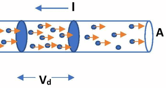
When an electric field is applied across the conductor, these free electrons experience a force that slightly biases their random motion in the direction opposite to the electric field (since electrons are negatively charged). This results in a small net velocity in one direction, known as the drift velocity.

Figure 2: Illustration of electron drift in a metallic conductor under an applied electric field.
Collisions and Resistance
As electrons move through the metal lattice, they experience frequent collisions with:
- Lattice ions (especially prominent at higher temperatures)
- Impurities in the metal
- Structural defects in the crystal lattice
- Other electrons
These collisions impede the flow of electrons and are responsible for the electrical resistance of the conductor. Between collisions, electrons accelerate due to the electric field, but their average velocity remains constant due to these frequent collisions. This phenomenon is called the steady-state drift velocity.
The average time between collisions is called the relaxation time (\(\tau\)), and it’s typically on the order of 10⁻¹⁴ seconds for metals at room temperature.
The drift velocity can be expressed as:
\[ v_d = \frac{eE\tau}{m} \]Where:
- \(v_d\) = drift velocity
- \(e\) = electron charge (1.602 × 10⁻¹⁹ C)
- \(E\) = electric field strength
- \(\tau\) = relaxation time
- \(m\) = electron mass (9.11 × 10⁻³¹ kg)
Current Density
The current density in a conductor is related to the drift velocity by:
Where:
- \(J\) = current density (amperes per square meter)
- \(n\) = number of free electrons per unit volume
- \(e\) = electron charge
- \(v_d\) = drift velocity
Thus, the total current through a conductor with cross-sectional area \(A\) is:
Factors Affecting Charge Flow
Several factors influence how efficiently electric charges flow through a metallic conductor:
1. Temperature
Temperature significantly affects the flow of electric charges in metals:
- Higher Temperature: Increases the vibrational energy of the metal lattice ions, which increases the frequency of collisions with free electrons, thus increasing resistance and reducing charge flow.
- Lower Temperature: Decreases lattice vibrations, reducing collisions and increasing conductivity.
- Superconductivity: At extremely low temperatures (near absolute zero), some materials exhibit superconductivity, where resistance drops to zero and charge flow occurs with perfect efficiency.
The relationship between resistance and temperature for most metals can be approximated by:
Where:
- \(R\) = resistance at temperature \(T\)
- \(R_0\) = resistance at reference temperature \(T_0\) (usually 20°C)
- \(\alpha\) = temperature coefficient of resistance
2. Material Properties
Different metals have varying abilities to conduct electricity due to their atomic structure:
| Material | Resistivity (Ω·m) at 20°C | Free Electron Density (m⁻³) |
|---|---|---|
| Silver | 1.59 × 10⁻⁸ | 5.85 × 10²⁸ |
| Copper | 1.68 × 10⁻⁸ | 8.47 × 10²⁸ |
| Gold | 2.44 × 10⁻⁸ | 5.90 × 10²⁸ |
| Aluminum | 2.82 × 10⁻⁸ | 6.02 × 10²⁸ |
| Iron | 9.71 × 10⁻⁸ | 1.70 × 10²⁸ |
3. Conductor Dimensions
The physical dimensions of a conductor directly affect its resistance and, consequently, the flow of electric charges:
Where:
- \(R\) = resistance (ohms)
- \(\rho\) = resistivity of the material (ohm-meters)
- \(L\) = length of the conductor (meters)
- \(A\) = cross-sectional area of the conductor (square meters)
4. Applied Electric Field
The strength of the applied electric field directly affects the drift velocity of electrons:
- Stronger electric field → greater force on electrons → higher drift velocity → larger current
- The relationship is linear for most metallic conductors (Ohm’s Law): \(J = \sigma E\) where \(\sigma\) is the conductivity
5. Impurities and Defects
The presence of impurities and structural defects in the metal crystal lattice creates additional scattering centers for electrons, increasing resistance and reducing charge flow:
- Point defects: Vacancies, interstitials, and substitutional impurities
- Line defects: Dislocations
- Surface defects: Grain boundaries in polycrystalline metals
Practical Implication: This is why high-purity copper is used for electrical wiring, and why annealing (heat treatment) can improve conductivity by reducing defects in the crystal structure.
Numerical Examples
Example 1: Calculating Drift Velocity
Problem: A copper wire with a cross-sectional area of 2.0 mm² carries a current of 5.0 A. Given that copper has approximately 8.5 × 10²⁸ free electrons per cubic meter, calculate the drift velocity of the electrons.
Solution:
We can use the relation between current, electron density, charge, area, and drift velocity:
\( I = nev_dA \)
Rearranging to find drift velocity:
\( v_d = \frac{I}{neA} \)
Given values:
- \( I = 5.0 \text{ A} \)
- \( n = 8.5 \times 10^{28} \text{ m}^{-3} \)
- \( e = 1.6 \times 10^{-19} \text{ C} \)
- \( A = 2.0 \text{ mm}^2 = 2.0 \times 10^{-6} \text{ m}^2 \)
Substituting these values:
\( v_d = \frac{5.0}{(8.5 \times 10^{28}) \times (1.6 \times 10^{-19}) \times (2.0 \times 10^{-6})} \)
\( v_d = \frac{5.0}{2.72 \times 10^4} \)
\( v_d = 1.84 \times 10^{-4} \text{ m/s} \)
Conclusion: The drift velocity of electrons in the copper wire is approximately 0.184 mm/s, which is remarkably slow compared to the random thermal velocity (about 10⁶ m/s). This slow drift velocity is sufficient to produce significant current because of the enormous number of electrons involved.
Example 2: Effect of Temperature on Resistance
Problem: A copper wire has a resistance of 10.0 Ω at 20°C. The temperature coefficient of resistance for copper is 3.9 × 10⁻³ °C⁻¹. Calculate the resistance of the wire at 80°C.
Solution:
We can use the temperature dependence formula:
\( R = R_0[1 + \alpha(T – T_0)] \)
Given values:
- \( R_0 = 10.0 \text{ Ω} \) (resistance at 20°C)
- \( \alpha = 3.9 \times 10^{-3} \text{ °C}^{-1} \) (temperature coefficient)
- \( T_0 = 20 \text{ °C} \) (reference temperature)
- \( T = 80 \text{ °C} \) (final temperature)
Substituting these values:
\( R = 10.0 \times [1 + 3.9 \times 10^{-3} \times (80 – 20)] \)
\( R = 10.0 \times [1 + 3.9 \times 10^{-3} \times 60] \)
\( R = 10.0 \times [1 + 0.234] \)
\( R = 10.0 \times 1.234 = 12.34 \text{ Ω} \)
Conclusion: The resistance of the copper wire increases from 10.0 Ω to 12.34 Ω when the temperature rises from 20°C to 80°C. This represents a 23.4% increase in resistance, illustrating how significantly temperature can affect the flow of charges in a metallic conductor.
Example 3: Current Density Calculation
Problem: An aluminum wire with a cross-sectional area of 4.0 mm² carries a current of 10 A. Calculate the current density in the wire and the electric field strength if the resistivity of aluminum is 2.82 × 10⁻⁸ Ω·m.
Solution:
Current density is given by:
\( J = \frac{I}{A} \)
Given values:
- \( I = 10 \text{ A} \)
- \( A = 4.0 \text{ mm}^2 = 4.0 \times 10^{-6} \text{ m}^2 \)
Substituting:
\( J = \frac{10}{4.0 \times 10^{-6}} = 2.5 \times 10^6 \text{ A/m}^2 \)
Using Ohm’s Law in its microscopic form:
\( J = \frac{E}{\rho} \)
Where \(\rho\) is the resistivity. Rearranging to find the electric field strength:
\( E = J \times \rho \)
\( E = 2.5 \times 10^6 \times 2.82 \times 10^{-8} = 0.0705 \text{ V/m} \)
Conclusion: The current density in the aluminum wire is 2.5 × 10⁶ A/m² and the electric field strength is approximately 0.0705 V/m.
Applications and Implications
Understanding the flow of electric charges in metallic conductors has numerous practical applications:
1. Electrical Wiring and Power Transmission
The principles of charge flow guide the design of:
- Power transmission lines (typically aluminum or copper)
- Household electrical wiring (copper)
- Electronic circuit interconnects
Engineers must consider factors like temperature rise, voltage drop, and current-carrying capacity, all of which are directly related to how charges flow through conductors.
2. Electronic Device Design
In electronic devices:
- Conductors are used for interconnects and pathways for current
- Understanding charge flow helps in designing devices that operate within temperature limits
- Miniaturization of electronics requires understanding how charge flow behaves at very small scales
3. Material Science and Development
Research continues into:
- High-temperature superconductors for lossless power transmission
- Novel conductor materials with improved properties
- Nanoscale conductors where quantum effects become important
4. Electromagnetism
The movement of charges in conductors creates magnetic fields according to Ampere’s Law. This principle is fundamental to the operation of:
- Electric motors
- Generators
- Transformers
- Electromagnets


