Magnetic Effects of Electric Current Class 10 Notes
Class 10 Complete Notes | Electromagnets, Motors, Generators & Applications
What You’ll Learn:
1 Fundamentals of Magnetism
Magnetic Field Lines
Key properties of magnetic field lines around a bar magnet:
- Originate from North pole, terminate at South pole
- Never intersect each other
- Denser near poles (stronger field)
- Closed continuous curves
Field direction: N→S outside magnet, S→N inside
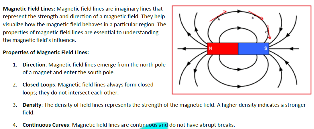 >
>Fig 1.1: Field lines of bar magnet
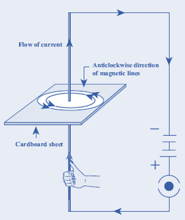
Right-Hand Thumb Rule
Determines magnetic field direction around current-carrying conductor:
- Grasp wire with right hand
- Thumb points in current direction (→)
- Fingers curl in field direction
Application: Used to find polarity of electromagnets
 >
>2 Electromagnets and Solenoids
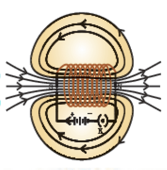
Solenoid
A coil of wire that produces magnetic field when current passes:
- Field lines: Similar to bar magnet
- Strength depends on:
- Number of turns (∝ n)
- Current (∝ I)
- Core material (soft iron enhances)
Magnetic field inside solenoid: B = μ₀nI
 >
>Electromagnet vs Permanent Magnet
| Feature | Electromagnet | Permanent Magnet |
|---|---|---|
| Strength | Adjustable (depends on I) | Fixed |
| Polarity | Reversible | Fixed |
| Uses | Cranes, MRI, Relays | Compass, Speakers |
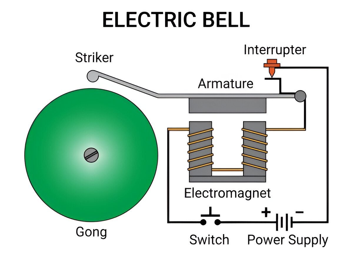
Real-World Application: Electric Bell
- Button pressed → circuit completes
- Electromagnet attracts hammer
- Hammer strikes gong (sound)
- Circuit breaks → process repeats
 >
>3 Fleming’s Hand Rules
Fleming’s Left-Hand Rule (Motor Rule)
Determines force direction on current-carrying conductor in magnetic field:
- Extend thumb, index, middle finger mutually perpendicular
- Index = Field (N→S)
- Middle = Current (+→-)
- Thumb = Force direction
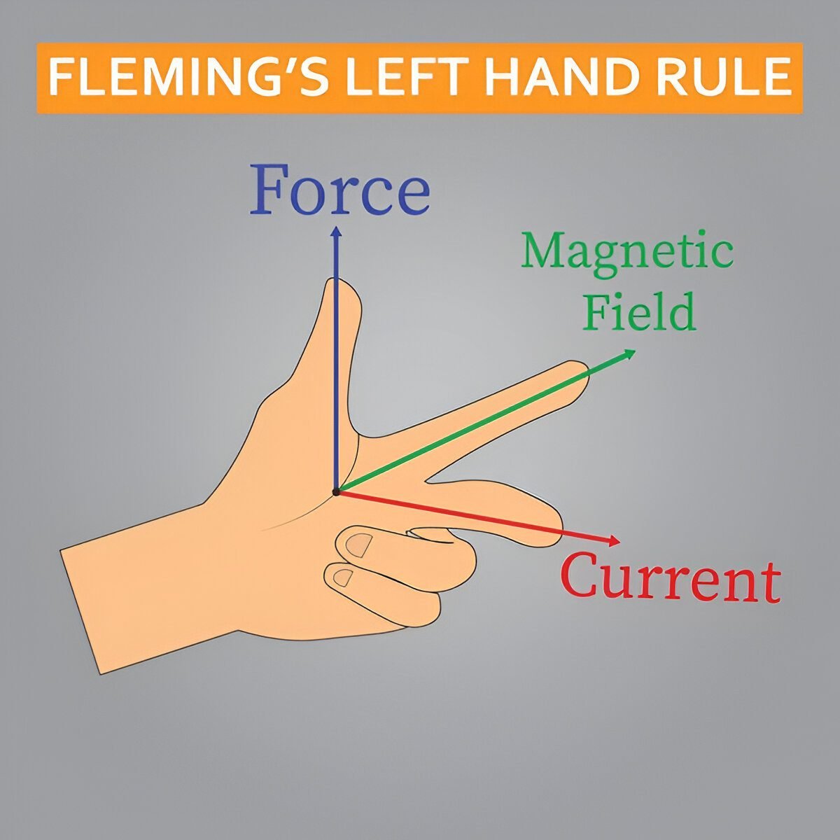 >
>Application: Used in electric motors
Fleming’s Right-Hand Rule (Generator Rule)
Determines current direction in conductor moving through magnetic field:
- Extend thumb, index, middle finger mutually perpendicular
- Thumb = Motion
- Index = Field (N→S)
- Middle = Induced current
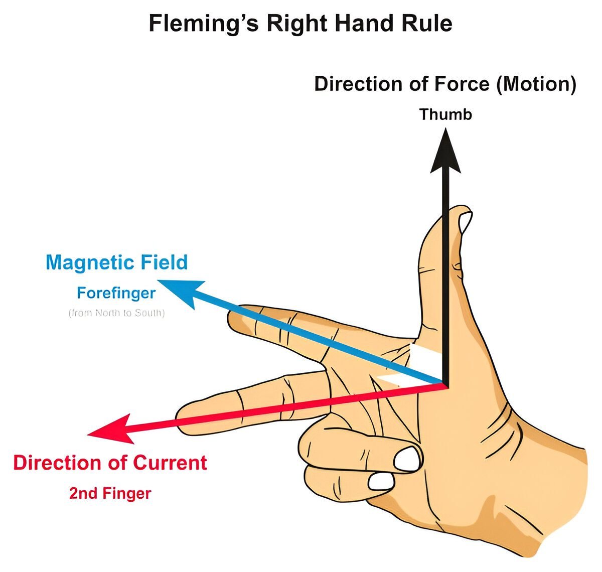 >
>Application: Used in generators
Memory Tip
“Left for Motor, Right for Generator” – Remember the ‘L’ in Left aligns with ‘L’ in Motor (both have 5 letters), while ‘R’ in Right aligns with ‘G’ in Generator.
4 Electric Motor
DC Motor Construction
Key components of a 4-pole DC motor:
- Armature: Rotating coil (ABCD)
- Field Magnets: Static N-S poles
- Split-ring Commutator: Reverses current every half-rotation
- Brushes: Carbon contacts to commutator
Force on conductor: F = IBL (B=magnetic field, L=length)
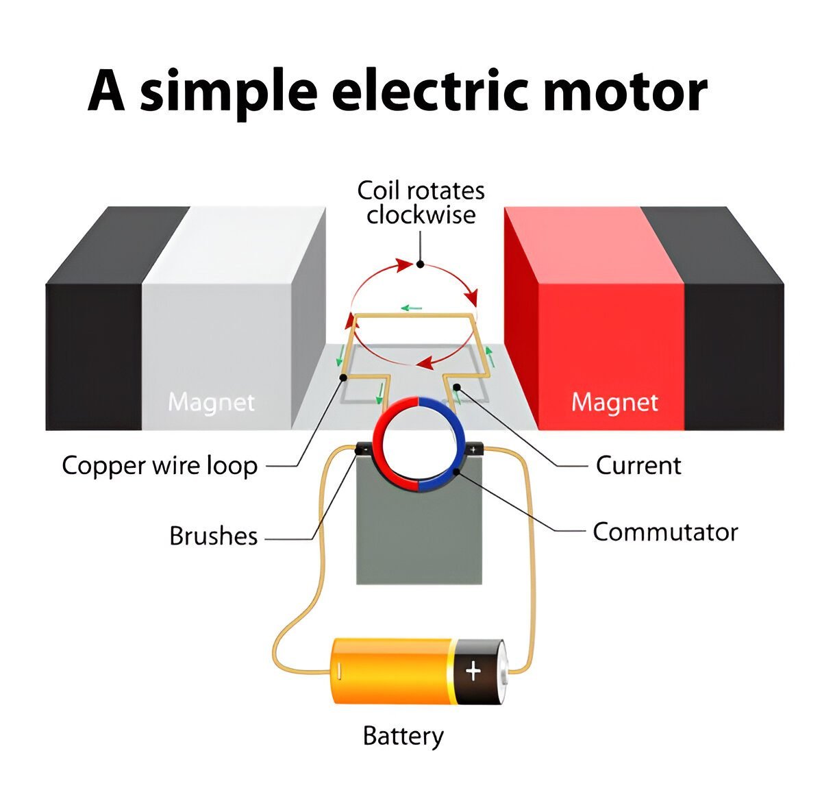 >
>Working Principle
- Current flows through armature via brushes
- Armature experiences torque (Fleming’s LHR)
- At 90° rotation, commutator reverses current
- Continuous rotation achieved
 >
> >
>5 Electric Generator
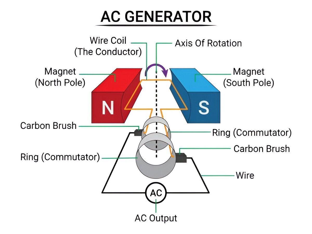
AC Generator
Converts mechanical to electrical energy (Fleming’s RHR):
- Uses slip rings (no current reversal)
- Produces alternating current (sinusoidal)
- Frequency = 50Hz (India), 60Hz (USA)
 >
>DC Generator
Similar to AC generator but with commutator:
- Split-ring commutator rectifies output
- Produces pulsating DC
- Used in automobiles (dynamo)
 >
>Numerical: EMF Calculation
Problem: A coil with 100 turns rotates at 50Hz in 0.1T field. Peak EMF if coil area is 0.01m²?
Given: N=100, B=0.1T, f=50Hz, A=0.01m²
Peak EMF (ε₀) = NBAω = NBA(2πf)
= 100 × 0.1 × 0.01 × 2 × 3.14 × 50
= 3.14 × 10 = 31.4V
6 Domestic Electric Circuits
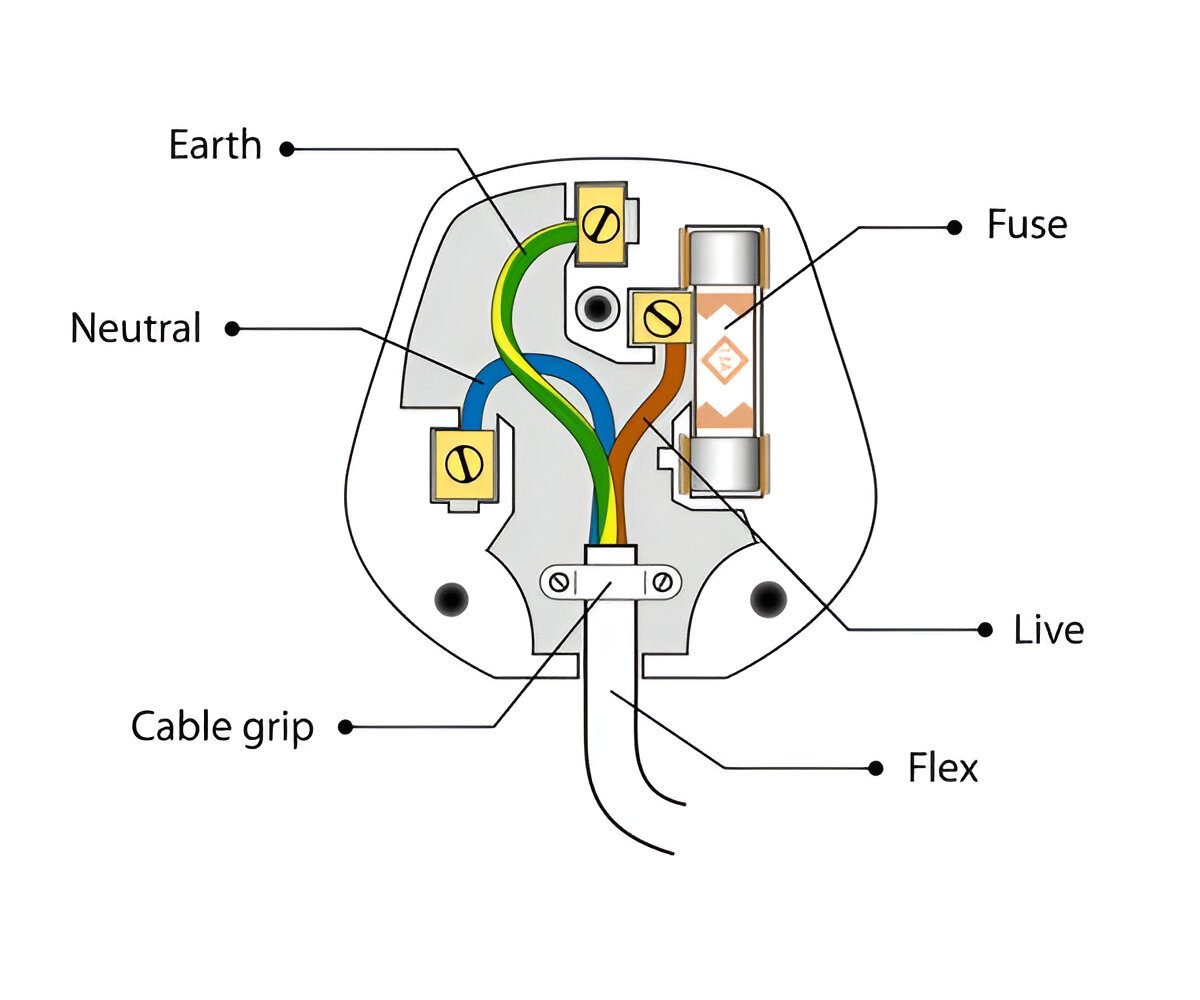
3-Pin Plug Wiring
Standard color codes and safety features:
- Live (Brown): 220V AC supply
- Neutral (Blue): Return path (0V)
- Earth (Green/Yellow): Safety wire to ground
- Fuse: Protects against overcurrent
Power (P) = VI cosφ (for AC)
 >
>Safety Devices
- Fuse: Thin wire melts at overcurrent (5A, 15A ratings)
- MCB (Miniature Circuit Breaker): Automatic switch for overload
- Earthing: Diverts leakage current to ground
Circuit Calculation
Problem: A 1500W heater runs on 220V. What fuse rating is appropriate?
I = P/V = 1500/220 ≈ 6.8A → Use 10A fuse
FAQs & Chapter Summary
Frequently Asked Questions
Why does a current-carrying conductor experience force in magnetic field?
Due to interaction between the conductor’s magnetic field and external field. Force direction is given by Fleming’s LHR (F = IBL).
What’s the difference between AC and DC generators?
| Feature | AC Generator | DC Generator |
|---|---|---|
| Rings | Slip rings | Split-ring commutator |
| Output | Sinusoidal AC | Pulsating DC |
Key Concepts
- Right-Hand Thumb Rule: Field around current-carrying wire
- Fleming’s LHR: Motor principle (Force direction)
- Fleming’s RHR: Generator principle (Current direction)
- Motor vs Generator: Energy conversion directions
- Domestic Safety: Fuse, earthing, MCB
Exam Tips
- Always draw diagrams for motor/generator questions
- Remember hand rules with mnemonics
- Fuse rating = 1.5× appliance current
Download complete notes with 20+ numerical problems and diagrams
Complete Chapter Notes
Access the detailed notes I’ve prepared covering all NCERT concepts, reactions, and important questions:


