Electric current represents the organized, directed transport of electric charge across a cross-section of a conductor under an applied potential difference. This chapter is one of the highest-weightage topics in NEET Physics (averaging 3 to 4 direct questions every year).
1. Electric Current & Microscopic Drift Velocity
Electric current I is a scalar quantity defined as the rate of charge flow:
Iavg = ΔqΔt,
Iinst = dqdt
Note on Direction: Electric current is a scalar because it does not obey the laws of vector addition, even though it possesses a definite direction along the conductor. Conventional current flows from higher potential (+) to lower potential (-), which is opposite to the physical motion of electrons.
Thermal Motion vs. Drift Velocity
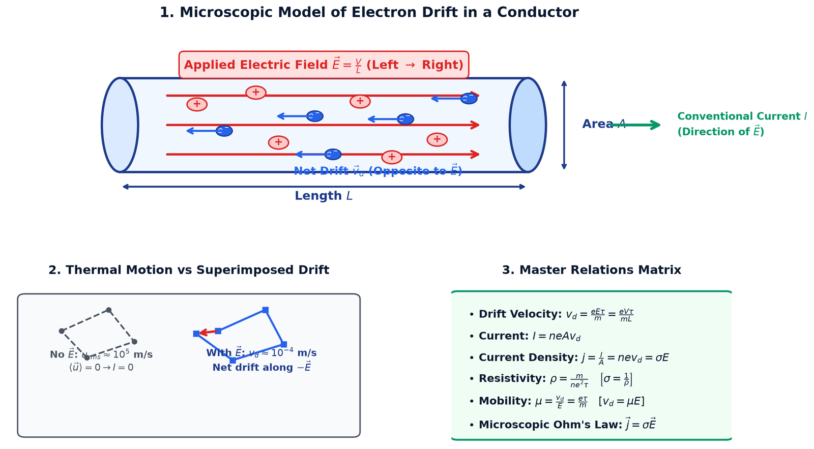
In the absence of an applied electric field, free conduction electrons move with high thermal speeds (urms ≈ 105 m/s) in random directions, undergoing frequent collisions with positive lattice ions. The average thermal velocity vector is zero: ⟨u⟩ = 0, resulting in zero net current.
When an electric field E = VL is established across a conductor of length L, each electron of charge -e and mass m experiences an electrostatic force F = -eE and an acceleration a = -eEm.
Between successive collisions, electrons acquire a steady average drift velocity vd directed opposite to E:
vd = e E τm
= e V τm L
where τ is the mean relaxation time (average time interval between two successive collisions, τ ≈ 10-14 s).
Relation Between Current, Drift Velocity & Current Density
Consider a conductor of cross-sectional area A with free electron number density n (electrons per unit volume):
Total charge in length L: q = (n A L) e
Time taken to drift through length L: t = Lvd
Electric Current: I = qt = n e A vd
Current Density j (vector): j = IA = n e vd = σ E
Figure 1: Microscopic model of electron drift, thermal collisions, and master relations matrix.
Electron Mobility (μ)
Mobility is defined as the magnitude of drift velocity acquired per unit applied electric field:
μ = vdE
= e τm
SI Unit: m2 · V-1 · s-1 or m · s-1 / (V · m-1). Mobility is always a positive scalar.
NEET Speed Tip — Drift Speed vs. Signal Speed:
The drift speed of electrons is exceedingly slow, typically vd ≈ 10-4 m/s (about 1 mm in 10 seconds). However, when a switch is closed, an electric bulb turns on almost instantaneously because the electromagnetic field propagates along the circuit wires at the speed of light (c ≈ 3 × 10⁸ m/s), setting all free electrons in motion simultaneously across the entire circuit.
2. Ohm's Law & Electrical Resistance
Ohm's Law: At constant physical conditions (such as temperature, strain, and pressure), the electric current flowing through a conductor is directly proportional to the potential difference applied across its ends:
V ∝ I &implies; V = I R
Microscopic Deduction of Ohm's Law
Substituting vd = e V τm L into I = n e A vd:
I = n e A e V τm L
= n e2 τ Am L V
&implies;
VI = mn e2 τ · LA = R
Comparing with R = ρ LA, we obtain the fundamental microscopic formulas for resistivity ρ and electrical conductivity σ:
ρ = mn e2 τ,
σ = 1ρ = n e2 τm
Key NEET Property of Resistivity (ρ):
Resistivity depends ONLY on the material of the conductor (via carrier density n) and its temperature (via relaxation time τ). It is completely independent of the dimensions (length L and cross-sectional area A) of the conductor.
Effect of Stretching / Compressing a Wire
When a wire of mass M, density d, and initial resistance R is stretched without altering its volume (V = A · L = \text{constant}):
Since A · L = \text{constant}, if length becomes L' = n L, area becomes A' = An.
New resistance: R' = ρ n LA / n = n2 R.
If radius changes to r' = rn, then area A ∝ r2, giving R ∝ 1r4.
For small percentage change (ΔL/L ≤ 5%):
ΔRR ≈ 2 ΔLL ≈ -2 ΔAA ≈ -4 Δrr
3. Temperature Dependence & Color Coding
The resistance of any material at temperature T is given by:
where α is the temperature coefficient of resistance (Unit: °C-1 or K-1).
Material Type
Sign of α
Physical Mechanism
Key Examples
Metals (Conductors)
α > 0 (Positive)
Carrier density n is constant; increased temperature intensifies lattice vibrations, reducing relaxation time τ (R ↑).
Copper, Aluminum, Silver
Semiconductors & Carbon
α < 0 (Negative)
Covalent bonds break rapidly, exponentially boosting carrier density n (n ∝ e-Eg/(2kBT)), overcoming decrease in τ (R ↓).
Silicon, Germanium, Carbon
Standard Resistance Alloys
α ≈ 0 (Near Zero)
Very high initial resistivity due to lattice disorder, with virtually no change in resistance over wide temperature ranges.
Manganin, Constantan, Nichrome
Electrolytes
α < 0 (Negative)
Higher temperature reduces viscosity and enhances ionic dissociation and ionic mobility (R ↓).
CuSO4, Dilute H2SO4
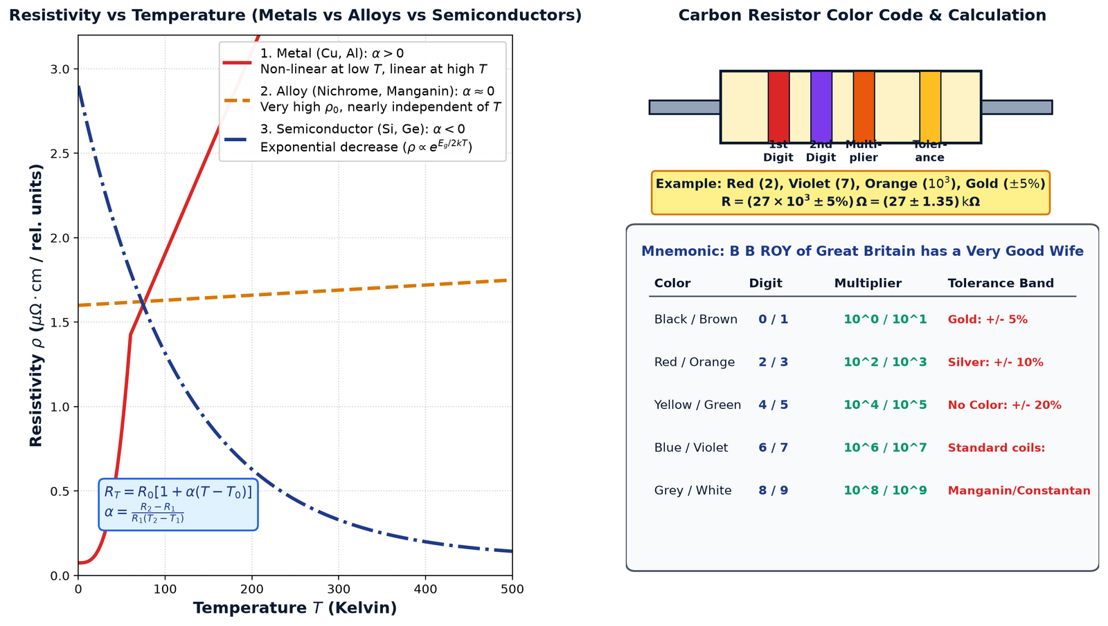
Figure 2: Resistivity vs Temperature curves for metals, alloys, and semiconductors alongside the 4-band color code chart.
Carbon Resistor Color Coding System
To identify the resistance value of a 4-band carbon resistor, memorize the standard mnemonic:
"B B ROY of Great Britain has a Very Good Wife"
Band 1: First significant digit of resistance.
Band 2: Second significant digit of resistance.
Band 3: Decimal multiplier (10n).
Band 4: Tolerance band: Gold (±5%), Silver (±10%), No Band (±20%).
R = (A B × 10C ± D)% Ω
4. Electric Energy, Power & Heating Effects
When a current I flows through a resistor R for time t under potential difference V, electrical energy is converted into thermal energy according to Joule's Law of Heating:
H = W = V I t = I2 R t = V2R t
P = Wt = V I = I2 R = V2R
Bulb Rating & Comparison (NEET Frequent Trap)
An electric appliance has rated power PR at rated voltage VR. Its internal resistance is fixed:
R = VR2PR
Bulbs in Series: Same current I flows through each bulb. Power dissipated P = I2 R ∝ R ∝ 1PR.
Golden Rule: In series, the bulb with the lower rated wattage glows brighter!
Bulbs in Parallel: Same voltage V across each bulb. Power dissipated P = V2R ∝ 1R ∝ PR.
Golden Rule: In parallel, the bulb with the higher rated wattage glows brighter!
5. Electromotive Force (EMF) & Grouping of Cells
Electromotive Force (EMF, E): The maximum potential difference between the terminals of a cell when no current is drawn from it (open circuit condition).
Internal Resistance (r): The opposition offered by the electrolyte and electrodes to the flow of ions inside the cell.
\text{1. Discharging (delivering current to external load } R\text{):} V = E - I r \quad (V < E)
\text{2. Charging (external source drives current into + terminal):} V = E + I r \quad (V > E)
\text{3. Open Circuit (} I = 0 \text{):} V = E
\text{4. Short Circuit (} R = 0 \text{):} I_{sc} = Er, \quad V = 0
Maximum Power Transfer Theorem
For an external load resistance R connected across a cell of EMF E and internal resistance r, the power dissipated in R is P = I2 R = E2 R(R + r)2.
P_{\text{ext}} \text{ is MAXIMUM when } R = r \implies P_{\text{max}} = E24r
NEET Fact: At maximum power transfer (R = r), electrical efficiency is only η = 50%!
6. Kirchhoff's Laws & Wheatstone Bridge
Kirchhoff's First Law (Junction Rule / KCL)
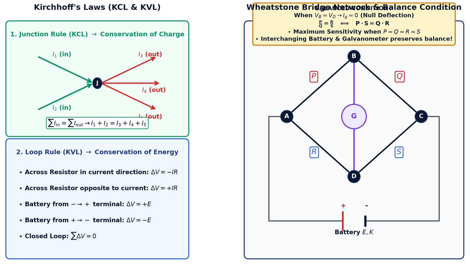
The algebraic sum of currents entering any electrical node is zero. This law directly reflects the fundamental Conservation of Electric Charge:
∑ I_{\text{in}} = ∑ I_{\text{out}} \implies ∑ I = 0
Kirchhoff's Second Law (Loop Rule / KVL)
In any closed mesh or loop of an electrical network, the algebraic sum of changes in potential is zero. This law directly reflects the Conservation of Energy:
∑ ΔV = 0 \implies ∑ E = ∑ I R
Figure 3: Kirchhoff's Junction and Loop rules with sign conventions, alongside the balanced Wheatstone Bridge network.
Balanced Wheatstone Bridge Principle
When four resistances P, Q, R, S form a closed quadrilateral mesh with a galvanometer connected between B and D, the bridge is balanced when potential V_B = V_D, meaning no current passes through the galvanometer (I_g = 0):
PQ = RS
⇔
P · S = Q · R
Conjugate Arms: Interchanging the battery and the galvanometer does not alter the balanced condition.
Maximum Sensitivity: The Wheatstone bridge is most sensitive to small changes when all four resistances are approximately equal (P ≈ Q ≈ R ≈ S).
7. Meter Bridge & Potentiometer
Meter Bridge (Slide Wire Bridge)
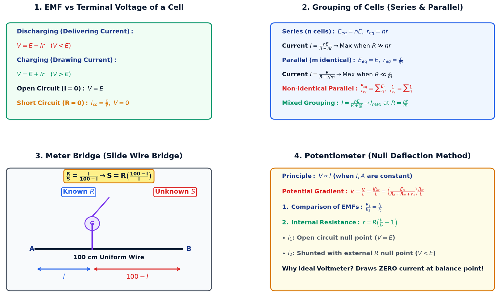
A practical laboratory application of the Wheatstone bridge utilizing a uniform resistance wire of length 100 cm (1 meter). If balance point is obtained at distance l from end A:
RS = l100 - l
&implies;
S = R · 100 - ll
Potentiometer Principle & Applications
A potentiometer consists of a long, uniform wire of high resistivity and low temperature coefficient (constantan or manganin). When a steady current flows through the wire from a primary driving cell E_0, the fall of potential across any portion of the wire is directly proportional to its length:
V ∝ l \implies V = k · l
where k is the Potential Gradient along the wire:
k = VL = I · R_wL = \left( E_0R_h + R_w + r_0 \right) R_wL
Figure 4: Real cell characteristics, grouping of cells, Meter Bridge setup, and Potentiometer applications.
Core Applications of Potentiometer:
Comparison of EMFs of Two Cells:
E1E2 = l1l2
Internal Resistance of a Cell:
Let l1 be the balance length on open circuit (E = k l1), and l2 be the balance length when shunted across external resistance R (V = k l2):
r = R \left( l1l2 - 1 \right) = R \left( l1 - l2l2 \right)
Why Potentiometer is an "Ideal Voltmeter":
An ordinary voltmeter has finite resistance and must draw a small current from the test circuit to produce a reading, thereby altering the terminal voltage to V = E - I r. A potentiometer, however, measures potential difference at the null balance point where current drawn from the test cell is strictly ZERO. Its effective resistance at the null point is infinite (R_{\text{eff}} = \infty), measuring true EMF!
Potentiometer Sensitivity Rules:
A potentiometer is more sensitive when its potential gradient k is smaller (a larger balance length corresponds to a given small potential difference). To increase sensitivity:
Increase the length of the potentiometer wire L.
Decrease the primary circuit current by increasing the rheostat resistance R_h.
Current Electricity — Master Formula Matrix
Every single high-yield equation required for NEET, organized logically with strict mathematical notation and standard units.
1. Drift Velocity & Microscopic Transport
Physical Quantity
Standard Formula
NEET Key Insight
Average Current
I = ΔqΔt = N et
Scalar quantity; does not obey vector addition laws.
Current from Orbiting Charge
I = qT = q f = q v2 π r
Frequently used for Bohr hydrogen atom orbit problems.
Drift Velocity (vd)
vd = e E τm = e V τm L
vd ≈ 10-4 m/s; directed opposite to applied E.
Conduction Current
I = n e A vd
For a wire of non-uniform cross-section, I is constant &implies; vd ∝ 1A.
Current Density (j)
j = IA = n e vd = σ E
Vector quantity! Direction is along E.
Electron Mobility (μ)
μ = vdE = e τm
Always positive. SI Unit: m2 · V-1 · s-1.
2. Resistance, Resistivity & Temperature
Physical Quantity
Standard Formula
NEET Key Insight
Electrical Resistance (R)
R = VI = ρ LA
Depends on material (ρ) and geometry (L, A).
Microscopic Resistivity (ρ)
ρ = mn e2 τ
Depends only on material (n) and temperature (τ).
Electrical Conductivity (σ)
σ = 1ρ = n e2 τm
SI Unit: Ω-1 · m-1 or S · m-1.
Wire Stretched by factor n
R' = n2 R
Constant volume (A L = \text{const}). If radius halved, R' = 16 R.
Small Percentage Stretch (≤5%)
ΔRR ≈ 2 ΔLL ≈ -4 Δrr
If length increases by 1%, resistance increases by 2%.
Temperature Dependence
RT = R0 [ 1 + α ΔT ]
α > 0 for metals; α < 0 for semiconductors; α ≈ 0 for nichrome.
Resistor Color Code
R = (A B × 10C ± D)% Ω
B B ROY of Great Britain has a Very Good Wife (0 to 9).
3. Electrical Power, Heating & Maximum Transfer
Physical Quantity
Standard Formula
NEET Key Insight
Electric Power (P)
P = V I = I2 R = V2R
1 kWh = 3.6 × 10⁶ J = 1 commercial unit of energy.
Rated Resistance of Bulb
R = VR2PR
Higher rated wattage means lower internal resistance.
Bulbs in Series
1Peq = 1P1 + 1P2
Lower rated wattage bulb glows BRIGHTER in series!
Bulbs in Parallel
Peq = P1 + P2
Higher rated wattage bulb glows BRIGHTER in parallel!
Maximum Power Transfer
P_{\text{max}} = E24 r
Occurs strictly when R_{\text{load}} = r_{\text{internal}}. Efficiency η = 50%.
r = R \left( l1l2 - 1 \right) = R \left( l1 - l2l2 \right)
l1 is open circuit; l2 is with shunt R.
20 Golden NEET Must-Know Facts & Traps
1 Current is a Scalar Quantity Trap Alert
Even though electric current has both magnitude and direction, it is a scalar because it does not obey vector addition (triangle law). Current at a junction is simply algebraically summed: I = I1 + I2.
2 Current Density is a Vector
Unlike current, current densityj is a true vector. Its direction is parallel to the electric field E and normal to the cross-sectional area: dI = j · dA.
3 In Non-uniform Conductor, Current is Constant High Yield
For a conductor of variable cross-section connected across a battery, in steady state:
I is constant throughout. But j, E, and vd vary inversely with area: j ∝ E ∝ vd ∝ 1A.
4 Drift Speed vs Electromagnetic Wave Speed
Electron drift speed is negligible (vd ≈ 10-4 m/s), but electric signals travel at nearly the speed of light (≈ 3 × 10⁸ m/s) because the electric field sets up almost instantaneously across the entire circuit.
5 Stretching a Wire by Percentage Frequent MCQ
When volume is constant: R ∝ L2 ∝ 1A2 ∝ 1r4.
If a wire is stretched by 0.1%, resistance increases by 2 × 0.1% = 0.2%.
If doubled in length (n = 2), new resistance is n2 R = 4 R (an increase of 300%!).
6 Temperature Coefficient α for Different Materials
α > 0 for pure metals (Cu, Ag); α < 0 for semiconductors (Si, Ge) and carbon; α ≈ 0 for alloys like manganin and constantan (used for standard resistance coils).
7 Superconductivity at Critical Temperature
At a critical temperature T_c, certain metals and alloys completely lose all electrical resistance (R = 0, \rho = 0). Mercury becomes superconducting at 4.2 \text{ K}.
8 Resistor Color Code: Silver vs Grey Trap Alert
In carbon resistors, Grey corresponds to digit 8, whereas Silver is only used as a multiplier (10-2) or a tolerance band (±10%). Never confuse grey with silver!
9 Terminal Voltage Can Exceed EMF! High Yield
When a cell is being charged by an external power source, current enters the positive terminal. Therefore, terminal voltage is V = E + I r > E.
10 Maximum Power Transfer Efficiency is 50%
A source delivers maximum power to an external load when R = r. Under this condition, half the total power is dissipated internally inside the source as heat; hence efficiency is strictly η = 50%.
11 Bulb Brightness Rule in Series vs Parallel
In series, current is identical, so P ∝ R ∝ 1Prated &implies; the bulb with LOWER rated wattage glows brighter!
In parallel, voltage is identical, so P ∝ 1R ∝ Prated &implies; the bulb with HIGHER rated wattage glows brighter!
12 Short Circuit vs Open Circuit of a Cell
Open Circuit:I = 0 \implies V = E (terminal voltage equals EMF).
Short Circuit:R = 0 \implies I_{sc} = Er, \quad V = 0 (all energy dissipated inside the cell itself).
13 Conservation Laws in Kirchhoff's Rules
Kirchhoff's Junction Rule (∑ I = 0) is based on Conservation of Electric Charge.
Kirchhoff's Loop Rule (∑ ΔV = 0) is based on Conservation of Energy.
14 Conjugate Arms of Wheatstone Bridge
If the positions of the battery and the galvanometer in a balanced Wheatstone bridge are interchanged, the balanced condition (PQ = RS) remains completely unchanged.
15 Sensitivity of Wheatstone Bridge
The Wheatstone bridge has maximum sensitivity when all four arm resistances are approximately equal in magnitude: P ≈ Q ≈ R ≈ S.
16 Meter Bridge End Corrections
In a meter bridge, contact resistances at the terminal copper strips create "end errors" (α1, α2). To eliminate end errors, the standard resistor R and unknown S are interchanged, and the average balance length is taken.
17 Why Potentiometer is an Ideal Voltmeter High Yield
A potentiometer operates on the null deflection method, drawing strictly zero current from the test cell at the balance point. Hence, its effective resistance is infinite (R_{\text{eff}} = \infty), measuring true EMF without any internal voltage drop!
18 Condition for Obtaining Balance on Potentiometer Wire
The EMF of the primary driver cell E_0 must always be strictly greater than the EMF of the test cell E (E_0 > E). If E_0 < E, the galvanometer will deflect in one direction across the entire wire, and no null point can ever be obtained!
19 How to Increase Potentiometer Sensitivity
Sensitivity is inversely proportional to potential gradient k = VL. To make it more sensitive (smaller k):
(1) Increase the length L of the potentiometer wire, or
(2) Increase resistance in the primary circuit (R_h) to decrease current I.
20 Equivalent of n Identical Resistors: Series vs Parallel
When n identical resistors R are connected in series: R_s = n R.
When connected in parallel: R_p = Rn.
The ratio is always:
RsRp = n2
8 High-Yield Solved Numericals — Current Electricity
Structured using the strict 3-Box Pedagogy: (1) Given & Core Concept, (2) Step-by-Step Mathematical Calculation with stacked fractions, and (3) NEET Speed Shortcut / Pro Tip.
Problem 1: Drift Velocity & Free Electron Density
A copper wire of cross-sectional area 1.0 × 10⁻⁶ m2 carries a steady electric current of 1.6 A. If the number density of free conduction electrons in copper is 8.0 × 1028 m-3, calculate the average drift velocity of the electrons. Also, calculate the time taken by an electron to drift through a 2.0 m long wire.
Box 1: Given Data & Core Concept
Cross-sectional area: A = 1.0 × 10⁻⁶ \text{ m}2
Current: I = 1.6 \text{ A}
Electron density: n = 8.0 × 1028 \text{ m}-3
Elementary charge: e = 1.6 × 10⁻¹⁹ \text{ C}
Wire length: L = 2.0 \text{ m}
Core Formula:I = n e A vd \implies vd = In e A and t = Lvd
Notice the denominator powers: 1028 × 10-19 × 10-6 = 103. Whenever I and e both have factors of 1.6, cancel them out immediately before multiplying to save 45 seconds! Keep in mind vd is always in the order of 10-4 \text{ m/s} for metals.
Problem 2: Wire Stretching & Percentage Resistance Change
A cylindrical metal wire having resistance 16 Ω is stretched uniformly such that its length increases by 25%. What is the new resistance of the wire, and what is the percentage change in its resistance?
Box 1: Given Data & Core Concept
Initial resistance: R = 16 \text{ Ω}
Length increase: ΔL = 0.25 L \implies L' = 1.25 L = 54 L
Core Concept: During stretching, volume V = A · L remains constant.
Therefore, A' = A1.25 = 45 A, giving R' = ρ L'A' \propto L2.
BIG NEET TRAP: The approximation ΔRR \approx 2 ΔLL = 50\% is ONLY valid for ΔL/L \le 5\%! For large changes like 25%, you MUST use the exact formula R' = n2 R. Here n = 1.25 \implies n2 = 1.5625, so \% \text{ change} = (1.5625 - 1) \times 100\% = 56.25\%.
Problem 3: Temperature Coefficient & Resistance Thermometer
A platinum resistance thermometer has a resistance of 5.00 Ω at 0 °C (ice point) and 5.93 Ω at 100 °C (steam point). When inserted into an unknown hot liquid bath, its resistance is measured to be 5.795 Ω. Determine the temperature of the bath.
Box 1: Given Data & Core Concept
Resistance at 0 °C: R0 = 5.00 \text{ Ω}
Resistance at 100 °C: R100 = 5.93 \text{ Ω}
Resistance at unknown temperature t: Rt = 5.795 \text{ Ω}
Never waste time computing the explicit value of α first! Directly use the ratio formula t = \frac{\Delta R_t}{\Delta R_{100}} \times 100. Division of differences immediately eliminates R_0 and α in one single step.
Problem 4: Balanced Wheatstone Bridge Circuit
In a Wheatstone bridge network ABCD, four resistors are arranged in arms AB, BC, CD, and DA as P = 10 Ω, Q = 30 Ω, S = 12 Ω, and R respectively. A galvanometer of resistance 50 Ω is connected between B and D, and a 12 V battery of negligible internal resistance is connected across A and C. Find (a) the value of resistance R for which the bridge is balanced, and (b) the total current supplied by the battery under this balanced condition.
Box 1: Given Data & Core Concept
Arm AB: P = 10 \text{ Ω}, Arm BC: Q = 30 \text{ Ω}
When finding battery current in a balanced Wheatstone bridge, immediately delete the central galvanometer branch! Then calculate branch currents directly:
I_1 = \frac{12}{40} = 0.30 \text{ A} and I_2 = \frac{12}{16} = 0.75 \text{ A}.
Total current: I = I_1 + I_2 = 0.30 + 0.75 = 1.05 \text{ A}. This takes under 15 seconds!
Problem 5: Non-Identical Cells in Parallel
Two cells of EMF E1 = 6.0 V and E2 = 4.0 V with internal resistances r1 = 1.0 Ω and r2 = 2.0 Ω respectively are connected in parallel with their positive terminals connected together. The combination is connected across an external load resistance of R = 4.0 Ω. Calculate (a) the equivalent EMF and equivalent internal resistance of the combination, (b) the terminal voltage across the load, and (c) the current delivered by each cell.
Notice: I2 < 0 means Cell 2 is actually being charged by the stronger Cell 1!
Box 3: NEET Speed Shortcut & Traps
When I_2 comes out negative, it indicates current is entering the positive terminal of Cell 2. Cell 1 supplies 10/7 \text{ A}, of which 8/7 \text{ A} goes to the external load and 2/7 \text{ A} recharges Cell 2! Conservation check: I_1 + I_2 = 107 - 27 = 87 = I.
Problem 6: Bulb Ratings & Series Dissipation
Two electric bulbs B1 and B2 rated (220 V, 60 W) and (220 V, 100 W) respectively are connected in series across a 220 V supply mains. Calculate (a) the resistance of each bulb, (b) the total power consumed by the series combination, and (c) the actual power dissipated in each individual bulb. Which bulb glows brighter?
Conclusion: Since P'_1 > P'_2 (23.44 W > 14.06 W), the 60 W bulb glows brighter!
Box 3: NEET Speed Shortcut & Traps
10-Second NEET Rule:
In Series: Power ∝ R ∝ 1P_{\text{rated}} &implies; Lower rated bulb glows BRIGHTER!
In Parallel: Power ∝ 1R ∝ P_{\text{rated}} &implies; Higher rated bulb glows BRIGHTER!
Problem 7: Meter Bridge with Parallel Shunt
In a standard meter bridge experiment, a balance point is obtained at a distance of 40 cm from the left end A when an unknown resistor X is in the left gap and a standard resistor Y = 12 Ω is in the right gap. If a resistor of 8 Ω is now connected in parallel with X in the left gap, calculate the new position of the balance point from end A.
3 l' = 100 - l' \implies 4 l' = 100 \implies l' = 1004 = 25 \text{ cm}
Box 3: NEET Speed Shortcut & Traps
When two equal resistors (both 8 Ω) are placed in parallel, their equivalent is halved (8/2 = 4 \text{ Ω}).
Since the left resistance dropped from 8 Ω to 4 Ω, the ratio becomes 4:12 = 1:3.
Dividing the 100 cm wire in a 1:3 ratio immediately gives l' = \frac{1}{4} \times 100 = 25 \text{ cm}. Mental math in under 10 seconds!
Problem 8: Potentiometer — Internal Resistance of a Cell
A potentiometer wire has a length of 400 cm and a resistance of 8.0 Ω. It is connected in series with a driver battery of EMF 2.0 V (zero internal resistance) and a protective series resistor Rs = 492 Ω. When a test cell is connected across the potentiometer wire, its balance length is found to be 250 cm on open circuit. When a shunt resistor of 10.0 Ω is connected across the test cell, the balance length shifts to 200 cm. Calculate (a) the potential gradient along the potentiometer wire, (b) the EMF of the test cell, and (c) the internal resistance of the test cell.
To find internal resistance r, you DO NOT need the potential gradient k!
Immediately apply the ratio: r = R \left( \frac{l_1}{l_2} - 1 \right) = 10 \left( \frac{250}{200} - 1 \right) = 10(1.25 - 1) = 2.5 \text{ Ω}. This eliminates 80% of computation work and avoids any conversion errors!
🎯 Current Electricity - Practice Quiz (30 High-Yield MCQs)
Instant retention practice with 30 high-yield NCERT multiple choice questions.
Q1. Which of the following statements concerning electric current is physically correct?
Explanation: Electric current has magnitude and direction along a conductor, but it adds algebraically at any junction according to Kirchhoff's Current Law (I = I1 + I2) rather than by vector addition rules (parallelogram law). Hence, it is a scalar quantity.
Q2. An electron in a hydrogen atom revolves around the nucleus in a circle of radius r = 5.3 × 10^-11 m with speed v = 2.2 × 10^6 m/s. The equivalent electric current associated with its orbital motion is approximately:
Explanation: Current I = e / T = e · v / (2πr) = (1.6 × 10^-19 × 2.2 × 10^6) / (2 × 3.1416 × 5.3 × 10^-11) = 3.52 × 10^-13 / 3.33 × 10^-10 ≈ 1.057 × 10^-3 A = 1.06 mA.
Q3. The drift velocity (v_d) of free electrons in a metallic conductor of length L and relaxation time τ when subjected to a potential difference V across its ends is given by:
Explanation: Applied electric field is E = V / L. The electrostatic force on an electron is F = eE, producing acceleration a = eE / m = eV / (mL). Therefore, average drift velocity is v_d = a · τ = (e V τ) / (m L).
Q4. A steady electric current flows through a metallic wire of non-uniform cross-section. Which of the following quantities remains constant along the length of the wire?
Explanation: In steady state, charge cannot accumulate anywhere along the wire. Hence, electric current I is strictly constant throughout. However, current density j = I/A, electric field E = j/σ, and drift speed v_d = I/(neA) all vary inversely with the cross-sectional area A.
Q5. A copper wire of radius r and length L has resistance R. If it is uniformly stretched until its radius becomes r/2, its new resistance will be:
Explanation: During stretching, the volume V = A · L is conserved. Since area A = πr^2, when radius is halved (r' = r/2), area becomes A' = A/4. Consequently, length becomes L' = 4L. The new resistance is R' = ρ L'/A' = ρ (4L) / (A/4) = 16 (ρ L/A) = 16 R.
Q6. If the length of a cylindrical metallic wire is stretched by 0.2% without altering its volume, the percentage increase in its electrical resistance is approximately:
Explanation: Since volume is constant (V = A · L = constant), R = ρ L/A = ρ L^2 / V ∝ L^2. For small fractional changes (ΔL/L ≤ 5%), taking differentials yields ΔR/R ≈ 2 (ΔL/L) = 2 × 0.2% = 0.4%.
Q7. The relaxation time (τ) in a metallic conductor:
Explanation: As the temperature of a metal increases, thermal vibrations of positive lattice ions intensify. The root-mean-square thermal speed of conduction electrons increases (u_rms ∝ √T), causing more frequent collisions and thus reducing the mean relaxation time τ (τ ∝ 1/√T).
Q8. Which of the following materials possesses a negative temperature coefficient of resistance (α < 0)?
Explanation: Germanium is an intrinsic semiconductor. With rising temperature, covalent bonds rupture rapidly, exponentially increasing the charge carrier density n (electrons and holes). This massive increase in n easily dominates the slight decrease in relaxation time τ, causing resistance to decrease (α < 0).
Q9. A carbon resistor is marked with four colored rings in sequence: Yellow, Violet, Brown, and Gold. The resistance value of this resistor is:
Explanation: Using 'B B ROY of Great Britain has a Very Good Wife': Yellow = 4, Violet = 7, Brown = 1 (multiplier 10^1 = 10), Gold = ±5% tolerance. Thus, R = (47 × 10 ± 5%) Ω = (470 ± 23.5) Ω.
Q10. The resistance of a platinum resistance thermometer is 2.0 Ω at 0 °C and 2.8 Ω at 100 °C. Its resistance at temperature t °C is 2.6 Ω. The value of t is:
Explanation: Using t = [(R_t - R_0) / (R_100 - R_0)] × 100 °C = [(2.6 - 2.0) / (2.8 - 2.0)] × 100 = (0.6 / 0.8) × 100 = (3/4) × 100 = 75 °C.
Q11. When n identical resistors each of resistance R are connected in series, the equivalent resistance is R_s. When connected in parallel, the equivalent resistance is R_p. The ratio R_s / R_p is:
Explanation: In series, R_s = n · R. In parallel, R_p = R / n. The ratio is R_s / R_p = (n R) / (R / n) = n^2.
Q12. A cell of EMF E and internal resistance r delivers current to an external load resistor R. The power dissipated in the load R is maximum when:
Explanation: According to the Maximum Power Transfer Theorem, power delivered by a real source to an external load is maximized when the load resistance equals the internal resistance of the source (R = r). At this point, P_max = E^2 / (4r).
Q13. When a real battery is delivering maximum power to an external load resistor (R = r), the electrical efficiency (η) of the circuit is:
Explanation: Efficiency η = (Useful Output Power / Total Power Generated) × 100% = (I^2 R / [I^2 (R + r)]) × 100%. When R = r, η = (r / 2r) × 100% = 50%. Exactly half of the generated energy is wasted as heat inside the battery's internal resistance.
Q14. Two electric bulbs rated 220 V, 40 W and 220 V, 100 W are connected in series across a 220 V supply mains. Which bulb will glow brighter?
Explanation: Rated resistance is R = V_R^2 / P_R, so R_40 = 220^2 / 40 = 1210 Ω and R_100 = 220^2 / 100 = 484 Ω. In a series combination, the same current I flows through both bulbs. Power dissipated is P = I^2 R ∝ R. Since R_40 > R_100, the 40 W bulb dissipates more power and glows brighter.
Q15. Two electric bulbs rated 220 V, 40 W and 220 V, 100 W are connected in parallel across a 220 V supply mains. Which bulb will glow brighter?
Explanation: In parallel across the rated 220 V supply, both bulbs experience the full 220 V. The power dissipated is P = V^2 / R = P_rated. Thus, the 100 W bulb dissipates 100 W while the 40 W bulb dissipates 40 W. Hence, the 100 W bulb glows brighter.
Q16. Under what condition can the terminal potential difference (V) across a cell be greater than its electromotive force (E)?
Explanation: During charging, an external power supply drives current into the positive terminal of the cell (opposite to normal discharging direction). The terminal potential difference becomes V = E + I · r, which is strictly greater than the EMF E.
Q17. A cell of EMF E = 1.5 V and internal resistance r = 0.5 Ω is short-circuited by a thick connecting wire of zero resistance. The short-circuit current and terminal voltage are:
Explanation: For short circuit, external resistance R = 0. The current is I_sc = E / r = 1.5 / 0.5 = 3.0 A. Terminal voltage is V = I · R = 3.0 × 0 = 0 V (or V = E - I r = 1.5 - 3.0 × 0.5 = 0 V).
Q18. Kirchhoff's first law (Junction rule, ∑ I = 0) and second law (Loop rule, ∑ ΔV = 0) are based respectively on the conservation of:
Explanation: Kirchhoff's Junction rule states that charge cannot accumulate at any junction (Conservation of Electric Charge). The Loop rule states that the net work done in moving a test charge around a closed electrostatic loop is zero (Conservation of Energy).
Q19. In a balanced Wheatstone bridge, the resistances in arms AB, BC, CD, and DA are 6 Ω, 12 Ω, X, and 3 Ω respectively. The value of unknown resistance X is:
Explanation: For balance: P / Q = R / S. Here AB = P = 6 Ω, BC = Q = 12 Ω, DA = R = 3 Ω, and CD = S = X. Balance equation gives: 6 / 12 = 3 / X ⇒ 1 / 2 = 3 / X ⇒ X = 6 Ω.
Q20. If the positions of the battery and the galvanometer in a balanced Wheatstone bridge are interchanged:
Explanation: The arms containing the battery and the galvanometer are conjugate arms. Interchanging them does not affect the balance condition (P/Q = R/S is equivalent to P/R = Q/S).
Q21. The sensitivity of a Wheatstone bridge is maximum when:
Explanation: The deflection of the galvanometer per unit fractional change in an arm resistance is highest when all four arms have nearly equal resistances (P ≈ Q ≈ R ≈ S).
Q22. In a meter bridge experiment, the null point is obtained at 30 cm from the left end when a known resistance of 14 Ω is connected in the right gap. The value of the unknown resistance in the left gap is:
Explanation: Using meter bridge balance condition: X / Y = l / (100 - l). Here l = 30 cm, 100 - l = 70 cm, and Y = 14 Ω. Thus, X = Y · [l / (100 - l)] = 14 × (30 / 70) = 14 × (3 / 7) = 6.0 Ω.
Q23. Why is a potentiometer strictly preferred over an ordinary voltmeter for precise measurement of EMF of a cell?
Explanation: An ordinary voltmeter has finite resistance and must draw a small current to produce a pointer deflection, thereby measuring terminal voltage V = E - Ir instead of true EMF E. A potentiometer operates on the null deflection method, drawing strictly zero current at balance (effective resistance is infinite), thus measuring exact EMF.
Q24. In a potentiometer arrangement, a cell of EMF 1.25 V gives a balance point at 35.0 cm length of the wire. If the cell is replaced by another cell and the balance point shifts to 63.0 cm, the EMF of the second cell is:
Explanation: From the principle of potentiometer: E1 / E2 = l1 / l2 ⇒ E2 = E1 × (l2 / l1) = 1.25 × (63.0 / 35.0) = 1.25 × 1.8 = 2.25 V.
Q25. To increase the sensitivity of a potentiometer, one should:
Explanation: Sensitivity is inversely proportional to potential gradient k = V / L. To increase sensitivity, k must be reduced. Increasing the wire length L decreases k, meaning a larger balance length is required for a given potential difference, enhancing resolution.
Q26. Two non-identical cells of EMFs E1 = 2 V and E2 = 1 V and internal resistances r1 = 1 Ω and r2 = 2 Ω are connected in parallel with opposing polarities (positive of E1 connected to negative of E2). The equivalent EMF of the combination is:
Q27. A piece of uniform resistance wire having resistance R is cut into 5 equal parts. These 5 parts are then connected in parallel. If the equivalent resistance of this parallel combination is R', then the ratio R / R' is:
Explanation: Each of the 5 pieces has resistance r = R / 5. Connecting 5 identical resistors of value R/5 in parallel gives R' = (R / 5) / 5 = R / 25. Therefore, R / R' = 25.
Q28. A uniform wire of resistance 20 Ω is bent into the shape of a complete circle. The effective resistance between two diametrically opposite points on the circle is:
Explanation: Diametrically opposite points divide the circle into two semicircular halves. Each half has a resistance of R/2 = 20 / 2 = 10 Ω. These two halves are connected in parallel across the diameter: R_eq = (10 × 10) / (10 + 10) = 5 Ω.
Q29. A cell of EMF E and internal resistance r is connected across an external resistance R. The graph of terminal potential difference (V) as a function of external resistance R is correctly described as:
Explanation: Terminal voltage is V = I · R = [E / (R + r)] · R = E / [1 + (r / R)]. At R = 0, V = 0. As R increases, V increases non-linearly. As R → ∞ (open circuit), V asymptotically approaches the open-circuit EMF E.
Q30. In a potentiometer wire experiment, if the EMF of the driver cell in the primary circuit is smaller than the EMF of the test cell in the secondary circuit (E_0 < E), what will be observed?
Explanation: The maximum potential difference that can be measured along the wire is the potential drop across the wire V_wire ≤ E_0. If the test EMF E > E_0, then even at the farthest end of the wire (L = 100%), the wire potential is less than E. Hence, current will continue flowing through the galvanometer in one direction, and no balance point can ever be reached.